
At 00:50 UTC on November 13, 2024, something went wrong deep inside Azure’s storage infrastructure. Within minutes, Blob Storage endpoints started returning errors. Downstream services — some belonging to major enterprise customers, others belonging to Azure’s own internal services — began failing in a cascade. Teams across the globe woke up to alerts. By 12:30 UTC, nearly twelve hours later, Microsoft engineers had finished restoring the last of the affected accounts.
The cause? A Traffic Manager profile had been accidentally deleted. That’s it. One deletion in the wrong place, during a routine service bifurcation operation, took storage accounts offline for twelve hours and affected services across multiple regions.
This is not an isolated story. Azure Storage — despite being engineered to survive disk failures, rack failures, datacenter fires, and DDoS attacks — has a documented list of incidents where the complexity of the system itself became the enemy. Understanding those incidents is actually the best way to understand how the engineering works, because each one illuminates a specific layer of a brilliantly designed but deeply intricate system.
This is the story of that system.
The Incidents That Reveal the Architecture
Before diving into how Azure Blob Storage works, let’s ground ourselves in what has actually gone wrong — because every incident is a window into the layers below.
🔴 Incident: The Deleted Traffic Manager Profile
November 13, 2024 · Duration: ~11.5 hours
Between 00:50 UTC and 12:30 UTC, a subset of Azure Blob Storage and Azure Data Lake Storage accounts became completely unreachable. The impact was widespread — many of the affected storage accounts were used by other Azure services and major software vendor solutions, creating a cascading failure well beyond storage itself.
The root cause: Traffic Manager profiles used to route blob and data lake storage API requests were unintentionally deleted. The Azure Storage service had been split into two separate services during a bifurcation. During the decommissioning of the old service, the subscription containing the Traffic Manager profiles was incorrectly assigned to the service being deprecated — and deleted along with it.
What this reveals: Even at planetary scale, Azure Blob Storage relies on routing infrastructure (Traffic Manager) that sits above the data layer. The data itself was safe the entire time — but without the routing layer, customers couldn’t reach it.
🔴 Incident: The Incomplete Allow List
July 18–19, 2024 · Duration: ~14.5 hours · Central US
During a routine update to the VM Host fleet, a workflow generated an “Allow List” update for Storage Scale Units — but due to backend infrastructure failures, the update was missing address range information for a significant number of VM Hosts. The workflow failed to detect the missing data and published the incomplete list across the region anyway.
Storage Servers rejected all VM disk requests from those VM Hosts. Virtual Machines lost access to their managed disks. Services built on top — including Azure Cosmos DB, Azure SQL, and Azure Kubernetes Service — began failing. The deployment workflow didn’t include sufficient checks for drops in VM availability, so it continued deploying the broken list before anyone caught it.
What this reveals: The compute-to-storage communication in Azure relies on access control lists at the Storage Scale Unit level. A missing entry doesn’t degrade gracefully — it fails shut, hard. This is by design for security, but it requires bulletproof deployment validation.
🔴 Incident: The Front-End Infinite Loop
Duration: ~11 hours
As part of a performance update, Microsoft tested a configuration change against Azure Table Storage Front-Ends in a flighting process — gradual deployment to a subset of customers. The test showed good performance. Engineers proceeded with a broader rollout. The problem: the configuration switch was incorrectly enabled for Azure Blob Storage Front-Ends, which exposed a latent bug causing those Front-Ends to enter an infinite loop, unable to accept further traffic.
Microsoft’s final Root Cause Analysis concluded: “there was a gap in the deployment tooling that relied on human decisions and protocol.”
What this reveals: The Front-End layer is the entry point for every Blob Storage request. An infinite loop on every FE node simultaneously is a self-inflicted denial-of-service. It also shows why Table and Blob storage, though appearing similar to users, have distinct internal code paths.
🔴 Incident: Rack Power Loss Cascades to Downstream Services
West Europe · Duration: ~5.5 hours
A power event impacted a subset of racks within a storage scale unit in an Azure West Europe datacenter. Customers experienced elevated latency, timeouts, and HTTP 500 errors. Because so many Azure services depend on storage, the impact cascaded to Virtual Machines, SQL Database, Cognitive Search, Backup, Application Insights, and others. Most services auto-recovered through built-in mechanisms — a portion required manual intervention.
What this reveals: When an entire storage scale unit is affected, the blast radius spreads to every service that depends on storage in that region. This is the physical reality the redundancy architecture is designed to contain — and sometimes contain imperfectly.
Each of these incidents tells us something specific about the layers below. Now let’s understand those layers from the ground up.
The Paper That Started It All
Most cloud services are black boxes. Azure Blob Storage is not. In October 2011, the Azure storage engineering team published “Windows Azure Storage: A Highly Available Cloud Storage Service with Strong Consistency” at the ACM Symposium on Operating Systems Principles (SOSP) — one of the most prestigious systems research venues in the world.
A year later came a second paper at USENIX ATC: “Erasure Coding in Windows Azure Storage” — introducing an algorithm they invented from scratch called Local Reconstruction Codes (LRC).
These papers sit alongside Google’s Bigtable and Amazon’s Dynamo as foundational reading in distributed systems. They’re why we can write an article like this — not because of leaks, but because the engineers were confident enough to show their work openly.
The Global Architecture: Stamps and Location Services
The first thing to understand about Azure Blob Storage is that it is not one system. It is a federation of self-contained clusters called Storage Stamps, coordinated by a global management plane called the Location Service.
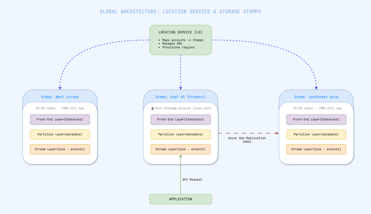
Figure 1 — The Location Service maps each storage account to a primary stamp and updates DNS. Geo-replication ships data asynchronously to a secondary stamp.
A Storage Stamp is a cluster of 10–20 racks of servers treated as a single deployment unit. All data belonging to a single storage account lives within one stamp. When you create an Azure Storage account, the Location Service assigns it to a primary stamp in your chosen region, stores the account metadata, and updates DNS to point your account’s endpoint at that stamp’s virtual IPs.
Stamps are utilized up to approximately 70%. When a stamp approaches that threshold, the Location Service begins migrating accounts to less-loaded stamps — macro-level load balancing happens by moving entire accounts, not rerouting individual requests.
The November 2024 incident hit exactly this layer. Traffic Manager profiles are part of the routing infrastructure that maps account DNS endpoints to specific stamps. When those profiles were deleted, the DNS entries became orphaned — the data sat safely inside the stamp, but the routing layer that told clients how to find it was gone.
Inside a Stamp: Three Layers That Each Own a Job
Within each Storage Stamp, every request passes through three distinct architectural layers. These run on separate servers, can fail independently, and scale independently.
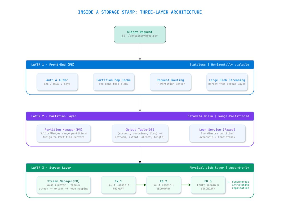
Figure 2 — A request flows through three layers. Front-End is stateless. Partition Layer is the metadata brain. Stream Layer owns the bits on disk.
Layer 1: Front-End (FE) — The Stateless Gateway
Every request hits a Front-End server first. The FE layer is completely stateless — any FE server can handle any request. The FE:
- Authenticates the request (SAS tokens, managed identity, account keys)
- Looks up the partition map from its local cache to find which Partition Server owns the target blob
- Forwards the request to the correct Partition Server
- For large blob reads, can stream data directly from the Stream Layer, bypassing the Partition Layer entirely
The Front-End Infinite Loop incident demonstrated what happens when FE servers malfunction at scale: they can’t accept new traffic, and everything built on top immediately starts failing.
Layer 2: Partition Layer — The Metadata Brain
The Partition Layer knows what every blob is and where it lives. It maintains a structure called the Object Table (OT) — a massive range-partitioned distributed database. Every row maps:
(account, container, blob_name) → (stream, extent, offset, length)
The OT is sharded into RangePartitions — contiguous row ranges assigned to individual Partition Servers. A Partition Manager can split busy partitions and reassign them. A Lock Service running Paxos consensus ensures only one server believes it owns a given range at any time — preventing split-brain scenarios.
This is also where inter-stamp (geo) replication originates. The partition layer asynchronously ships data to secondary stamps after acknowledging writes locally.
Layer 3: Stream Layer — Bits on Disk
The Stream Layer is the actual distributed file system. It doesn’t understand what a “blob” is — it only knows about streams, extents, and blocks.
| Concept | Size | Role |
|---|---|---|
| Block | Up to 4 MB | Atomic unit of read/write; checksummed |
| Extent | ~1 GB | Unit of replication; stored as a file on local filesystem |
| Stream | Many extents | What blobs are built from; append-only |
Critically, streams are append-only and immutable. Once an extent is sealed (closed for writes), it can never be modified. This immutability is what makes the system’s consistency guarantees tractable at scale — there are no in-place updates to coordinate across replicas.
Two components manage the Stream Layer:
- Stream Manager (SM): A Paxos-replicated cluster that maintains the mapping of streams → extents → Extent Nodes. It performs health monitoring, assigns new extent nodes, handles garbage collection, and triggers re-replication when nodes fail.
- Extent Nodes (EN): The actual storage workers. Each EN manages a group of physical disks, stores assigned extent replicas, and communicates with peer ENs for replication.
How Data Is Actually Written and Stored
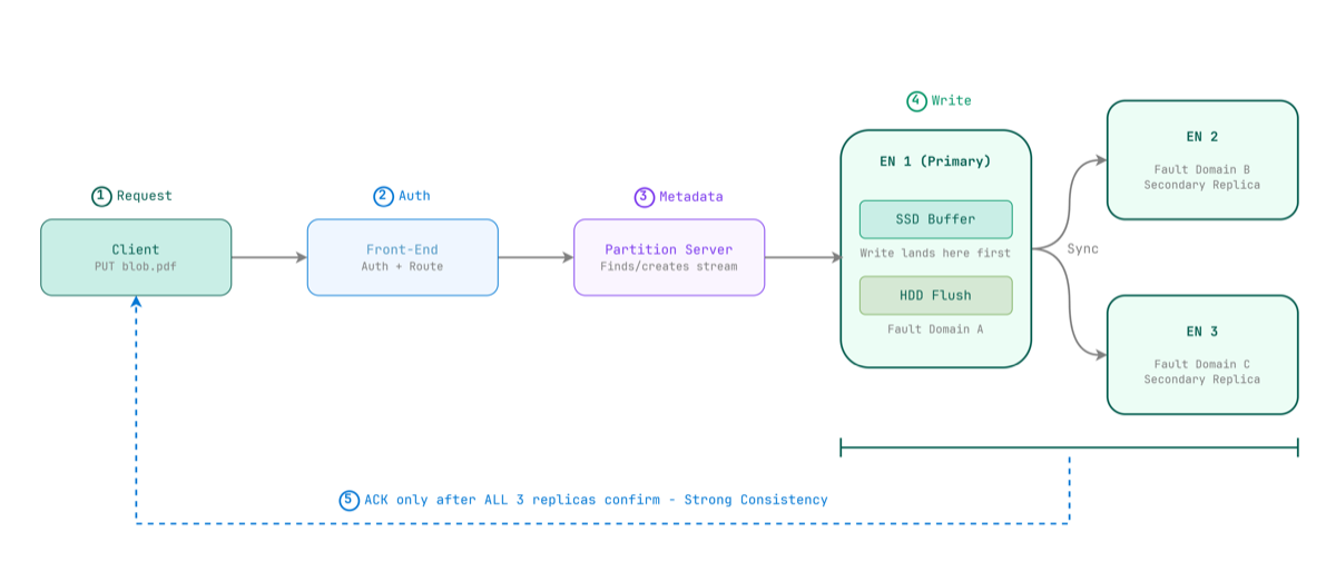
Figure 3 — A write is only acknowledged after all three Extent Nodes confirm. This is what strong consistency means in practice.
When you write a blob, the Partition Server instructs the Stream Layer to append data to the current open extent. The primary Extent Node writes the data — landing first on its dedicated SSD write buffer for speed — then synchronously replicates to two secondary Extent Nodes in separate fault domains.
The ACK only goes back to the client once all three nodes confirm.
This is what strong consistency means in Azure Blob Storage: once a write is acknowledged, any subsequent read from any node will return that data. No eventual consistency. No read-your-writes surprises.
The three replicas are deliberately placed across separate fault domains and upgrade domains within the stamp:
- A fault domain is a group of nodes sharing hardware failure risk (e.g., same rack, same power supply)
- An upgrade domain is a group of nodes updated together during maintenance
This placement means a rack-level failure won’t take out all three copies of your data simultaneously.
The SSD Write Buffer Trick
Azure Blob Storage runs primarily on HDDs — not SSDs — for bulk data. This is an economics decision at exabyte scale. HDDs are orders of magnitude cheaper per terabyte.
But HDDs are slow. Azure handles this with two techniques:
- SSD Write Buffer: Each Extent Node allocates a dedicated SSD as a write buffer. Writes land on SSD first (fast), then flush to HDD in the background. This gives write latency that feels SSD-fast at HDD storage cost.
- Deadline I/O Scheduling: A custom I/O scheduler spreads requests across HDDs based on current load. If an Extent Node can’t service a read within its deadline, it immediately returns an error — allowing the client to retry at another EN rather than waiting for a slow disk seek. This keeps 99th-percentile latency predictable under load.
The Erasure Coding Innovation: Why Azure Invented LRC
Storing three full copies (3x replication) is simple and fast — but unsustainable at exabyte scale. Once an extent is sealed, Azure applies erasure coding to dramatically reduce storage overhead.
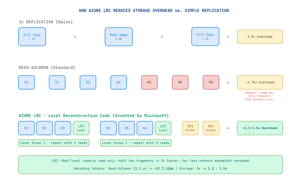
Figure 4 — LRC creates local parity groups so that most failures require reading only a small local group — not all fragments across the entire cluster.
Standard erasure coding (Reed-Solomon) splits data into k data fragments and adds m parity fragments. You can reconstruct the original from any k of the total — but when a disk fails, you must read all remaining k data fragments from across the network to reconstruct the missing piece. At exabyte scale, this creates enormous repair bandwidth.
Microsoft wasn’t satisfied with this. They invented Local Reconstruction Codes (LRC) — published at USENIX ATC 2012 — specifically for blob storage workloads.
How LRC Works
The key insight: most failures in a real datacenter are local — a single disk, a single server, a single rack. You don’t need global parity for local failures. You just need local parity.
LRC creates two types of parity fragments:
- Local parity: Covers a small local group of data fragments. Recovers from local failures by reading only that small group.
- Global parity: Covers all fragments. Recovers from any combination of failures.
When a single disk fails, you only read fragments from its small local group — not all fragments from across the datacenter.
The Numbers
| Method | Storage Overhead | Repair Read Cost | Decode Latency (4 KB) |
|---|---|---|---|
| 3× Replication | 3.0× | N/A (full copy) | — |
| Reed-Solomon | ~1.75× | Read ALL k fragments | 13.2 µs |
| Azure LRC | 1.3–1.5× | Read local group only | 7.12 µs |
LRC reduces storage overhead from 3× all the way down to 1.3×–1.5×, while repair bandwidth falls to roughly half of Reed-Solomon. Erasure coding is applied only to sealed extents — active extents remain at 3× replication for write-path speed, then get re-encoded in the background once sealed.
The Redundancy Spectrum
Azure gives architects explicit control over the durability vs. cost trade-off:
| Option | Where Copies Live | Durability | Best For |
|---|---|---|---|
| LRS | 3 copies, same datacenter | 11 nines | Dev/test, non-critical |
| ZRS | 3 copies across AZs (sync) | 12 nines | Production, zone resilience |
| GRS | LRS + async copy to secondary region | 16 nines | Business-critical data |
| GZRS | ZRS + async copy to secondary region | 16 nines | Maximum resilience |
| RA-GRS / RA-GZRS | Same as above + readable secondary | 16 nines | Geo-distributed reads |
At 16 nines durability (99.99999999999999%), if you stored 10 million objects, you would statistically lose one object every 10 million years.
⚠️ GRS does not mean zero RPO. Inter-stamp replication is asynchronous. Without Geo Priority Replication enabled, there is no SLA on lag. With it enabled, Azure guarantees RPO ≤ 15 minutes for 99% of the billing month for block blob data. Monitor the Geo Blob Lag metric actively.
Two Replication Engines Under the Hood
Intra-stamp replication (synchronous): Handled by the Stream Layer. The primary Extent Node replicates to two secondaries before acknowledging the write. This gives strong consistency within the stamp.
Inter-stamp replication (asynchronous): Handled by the Partition Layer. Data is shipped to a secondary stamp in a different region after the local write is committed. This is how GRS/GZRS work — and why RPO is non-zero without Geo Priority Replication.
Durability Is Not Just Replication
Durability is not the same as availability.
Azure Storage uses CRC (cyclic redundancy checks) to continuously verify the integrity of stored data in the background. If corruption is detected at the block level, Azure automatically reconstructs the affected block from replicas or erasure-coded fragments and re-writes a clean copy — independent of client activity.
The blob layer adds further safety nets:
- Soft Delete: Keeps deleted blobs recoverable for a configurable retention period
- Versioning: Maintains history of previous blob states on modification
- WORM (Immutable Blob Storage): Locks blobs against modification for a configured period — legally defensible for financial, healthcare, and legal records
Both soft delete and versioning protect against accidental deletions and application-layer corruption — which replication alone cannot catch, since corruption is faithfully replicated along with the data.
The AI Era Is Rewriting the Scale Requirements
Azure Blob Storage was originally designed for cloud-era workloads — application files, backups, media, logs. The AI era has completely changed the requirements.
Training a large language model means reading terabytes or petabytes of data repeatedly at extremely high throughput, directly into GPUs. Azure has evolved its architecture to deliver exabytes of capacity and tens of terabytes per second of throughput from a single storage account. A single account can now scale to over 50 Tbps of read throughput.
The recently expanded maximum blob size — previewing at 200 TB per object (a 40× increase from the previous 5 TB limit) — was driven directly by AI checkpoint files and dataset shards that simply didn’t exist when the system was designed.
What the Incidents Teach Us for Architecture
1. Lock Your Critical Infrastructure
The Traffic Manager deletion happened because a subscription was wrongly decommissioned. Apply Azure Resource Locks (CanNotDelete) to all production routing and DNS resources.
2. Validate Deploys Against Availability Drops
The Allow List deployment continued even as VMs started failing. Build availability health checks into your pipelines that halt rollouts if error rates spike — at any layer, not just the service being updated.
3. Test Configuration Changes Across Each Blob Type Separately
Table and Blob storage share an FE layer but have separate code paths. Validate changes across each storage abstraction type explicitly in staging.
4. Never Serve Blob Storage Directly to End Users at Scale
Blob Storage is an origin, not a CDN. Put Azure CDN or Azure Front Door in front for any user-facing content. Let the CDN absorb read traffic; let Blob Storage focus on being the durable source of truth.
5. Randomize Blob Name Prefixes for High-Throughput Writes
Azure scales throughput by partition, keyed on the blob name prefix. If all blobs share the same prefix, you’ll hit one partition’s rate limits. Hash or randomize prefixes for high-throughput write workloads.
6. Enable Soft Delete and Versioning
Geo-replication faithfully copies corruption and accidental deletions. Soft delete and versioning protect against application-layer mistakes that redundancy alone cannot catch.
The Numbers in Context
| Metric | Value |
|---|---|
| Transactions per month | 1 quadrillion (1,000 trillion) |
| Data read/written monthly | 100+ exabytes |
| Peak read throughput (single account) | 50+ Tbps |
| Maximum blob size (preview) | 200 TB |
| Durability with geo-replication | 16 nines |
| Storage overhead after LRC erasure coding | 1.3–1.5× |
The team that built this started from first principles in 2008. They implemented Paxos consensus to coordinate the Stream Manager. They invented a new error-correction algorithm because Reed-Solomon wasn’t fast enough for their repair latency requirements. They engineered a three-layer architecture where each layer can fail and scale independently. And they published all of it openly — because confident engineers aren’t afraid of showing their work.
Through all the incidents described in this article — the deleted Traffic Manager profiles, the incomplete Allow Lists, the Front-End infinite loops, the power cascades — the underlying stream layer held. In every case, the raw data in the extent nodes was never at risk. What failed was always the routing, the configuration, the metadata, the access control — the operational layers built above the core storage engine.
That’s both the brilliance and the lesson. Building a system that never loses data is achievable. Building all the layers above it — reliably, at planetary scale, forever — is the real engineering challenge.
References
- Calder, B. et al. (2011). Windows Azure Storage: A Highly Available Cloud Storage Service with Strong Consistency. ACM SOSP 2011. PDF
- Huang, C. et al. (2012). Erasure Coding in Windows Azure Storage. USENIX ATC 2012. Link
- Microsoft Azure. (2024). Post Incident Review — Azure Storage — Unreachable Blob and Data Lake storage accounts (Nov 13, 2024). Link
- Futurum Group. (2024). Microsoft’s Central US Azure Outage: What Went Wrong? Link
- BleepingComputer. (2024). Major Microsoft 365 Outage Caused by Azure Configuration Change. Link
- Microsoft Azure Blog. (2024). Update on Azure Storage Service Interruption (Blob FE Infinite Loop). Link
- Microsoft Azure Blog. (2023). Reflecting on 2023 — Azure Storage. Link
- Microsoft Azure Blog. (2025). Azure Storage Innovations: Unlocking the Future of Data. Link
- NetApp Blog. (2025). Azure Storage: Behind the Scenes. Link
- Microsoft Learn. (2025). Data Redundancy — Azure Storage. Link
- Distributed Computing Musings. (2024). Paper Notes: Windows Azure Storage. Link